The SSP Traceability Workflow Guide is a supplementary documentation to the SSP Traceability Specification 1.0. While the SSP Traceability Specification 1.0 essentially describes a data format for STMD files in the sense of a normative document, the SSP Traceability Workflow Guide addresses how and in which way the SSP Traceability can be used in industrial practice. It thus addresses topics and answers questions that the SSP Traceability Specification 1.0 as a normative document cannot address and answer.
This is a development version of the SSP Traceability Workflow Guide. Releases and issues can be found on github.com/PMSFIT/SSPTraceabilityGuides.
1. Introduction
1.1. Purpose and structure of the user guide
The user guide is intended to provide information and examples of how the SSP Layered Standard Traceability can be applied. It is important to note that the Layered Standard SSP Traceability is in XML format, which is clearly structured and readable, but should be created and modified using appropriate tool support. This is comparable to the use of FMUs or SSP. Further introductory information is described in chapters 1-3 of the SSP LS Traceability [SSPLST].
2. Objectives, Structure, and Application of SSP Traceability
Objectives:
-
Structuring of information
-
Traceability of simulations and their results
-
Reuse of simulations
-
Use, exchange in heterogeneous simulation and IT infrastructures
-
Cooperation with partners
In the following it is described how the SSP Traceability STMD Schema supports the Credible Simulation Process [CSP].
| More information on the relationship between SSP LS Traceability and the Credible Simulation Process Framework can be found in section 2 of the SSP LS Traceability. |
The typical procedure in a development or simulation process is shown in Figure 1. Many recursions take place in such a process. The Credible Simulation Process (CSP) therefore does not represent the chronological sequence but the logical order of the sequence. This is required for traceability.
| The CSP is therefore a documentation schema and not a chronological process description. |
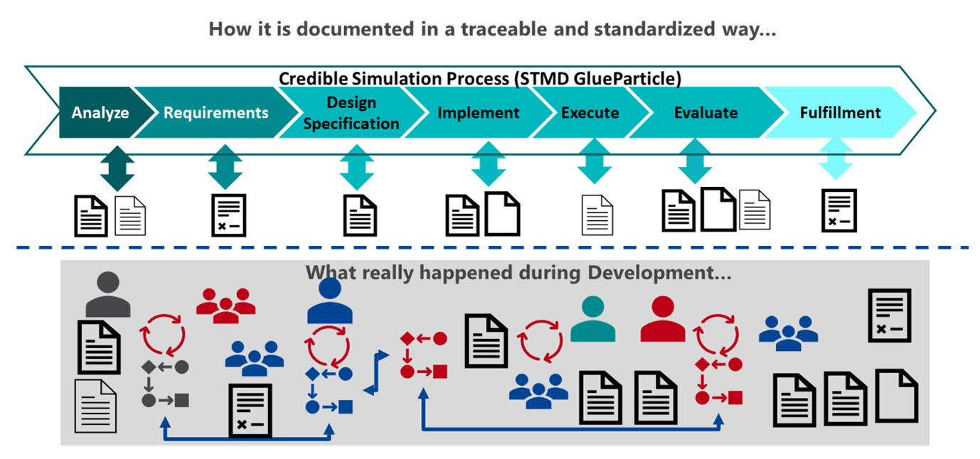
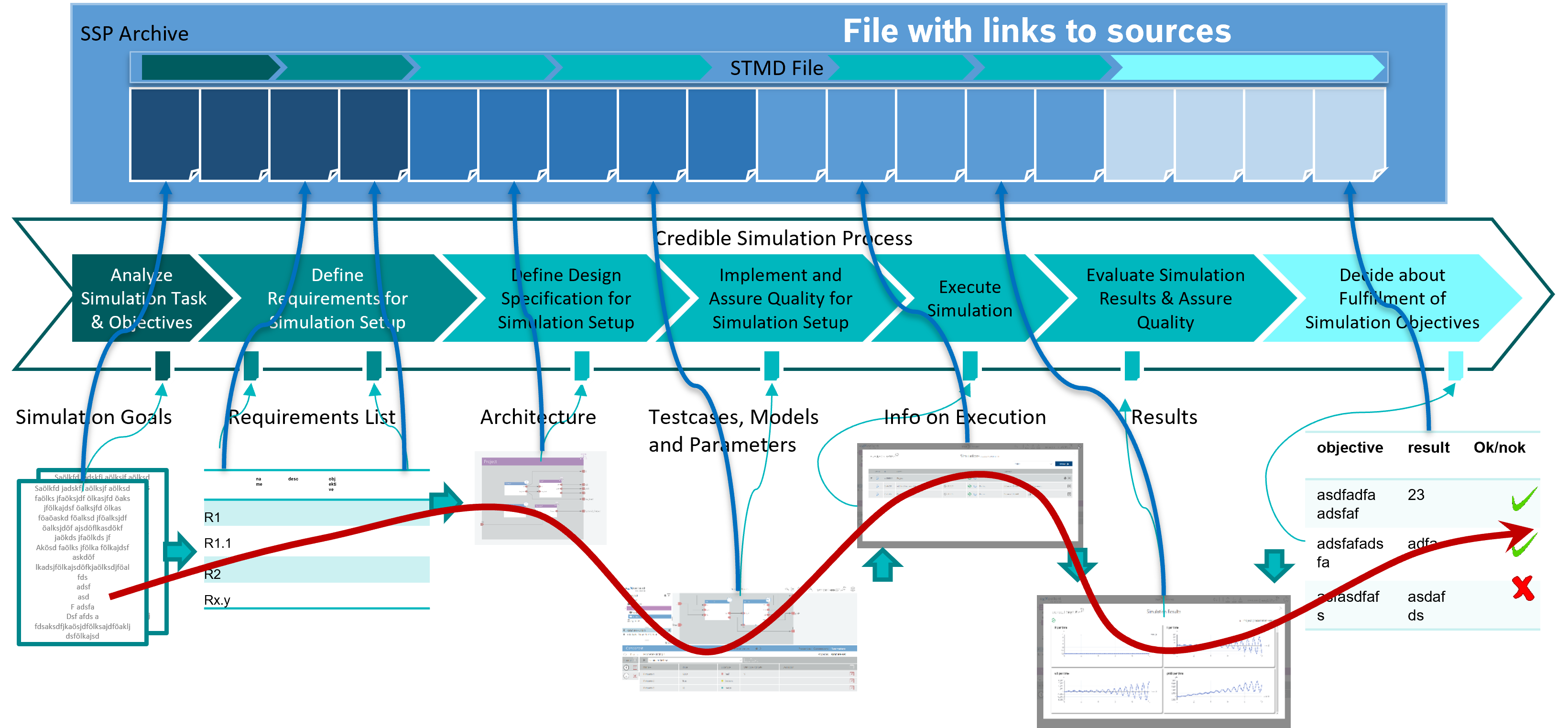
Figure 2 illustrates how the information, the CSP, and the corresponding SSP traceability data format “Simulation Task Meta Data” (STMD) interact with one another.
The STMD format is part of the information. The data is linked to the STMD XML schema file according to its type.
This STMD XML file with the links can then be saved or exchanged and forms the building block for traceability.
SSP LS Traceability requires that the import and export tools as well as the data management systems support this standard and this structure. However, no specifications are provided regarding how the data management tool must internally structure the data.
The following three layers should be distinguished in implementation and application (Figure 3):
-
Process
-
Structuring of information according to logical context
-
-
Data
-
Data and version management
-
-
Workflow
-
Interfaces corresponding to the application
-
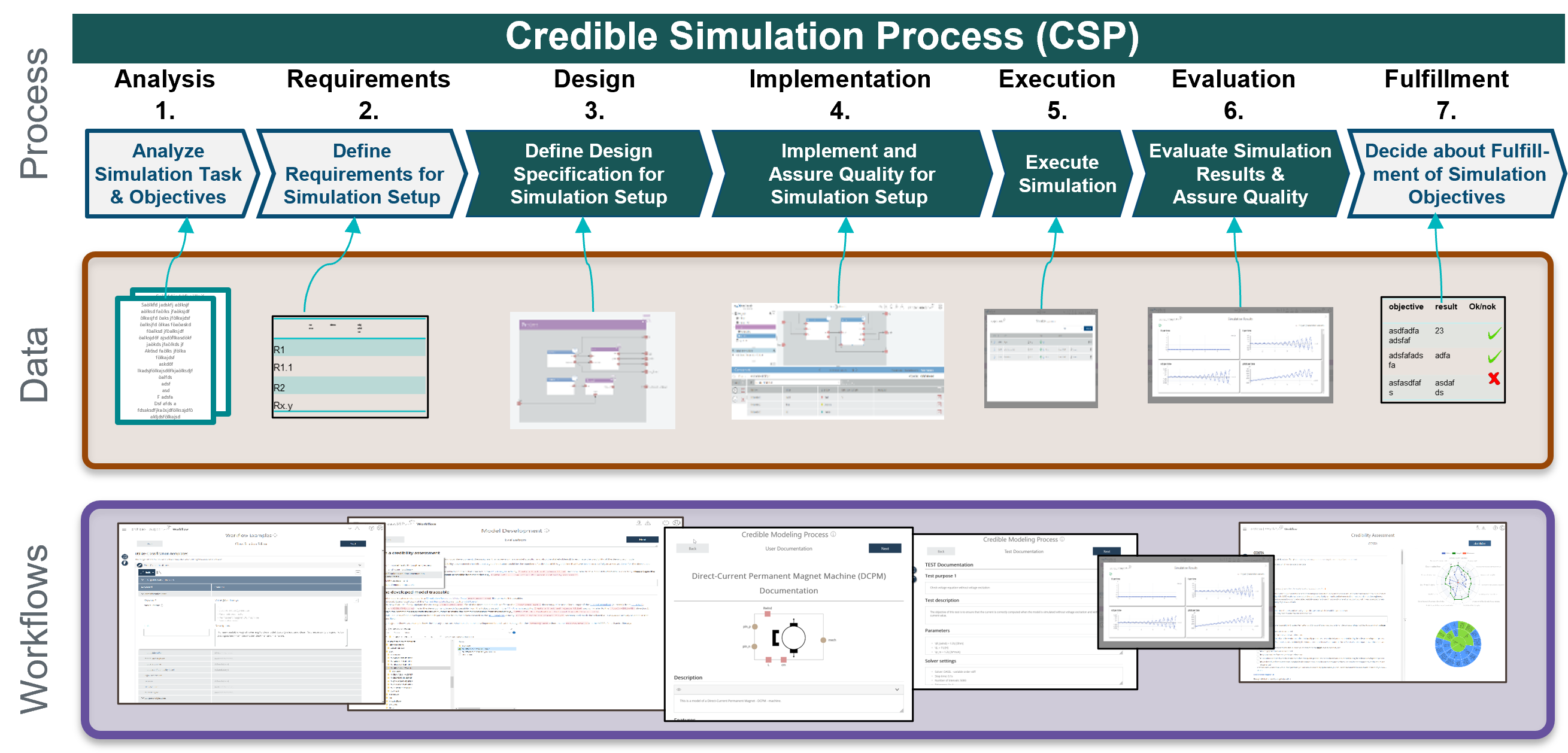
The SSP LS Traceability focuses on supporting the process level. Clear logical structuring as the basis for traceability. The data is linked to the SSP Traceability Schema. Links to any data management system can be used. For exchange with partners who do not have direct access to these systems, this data can be packaged and sent as part of an SSP container. The specifications of this structure are part of the SSP LS Traceability specification.
Users should only enter their information via a workflow interface and use the Credible Simulation Process indirectly. At the workflow interface, the information should be provided in the form and order that corresponds to typical use. Here, a mapping of names that are intuitively understandable for the user in the input masks to the IT systems' unique naming conventions should also take place. These naming conventions are usually not directly intuitive or cumbersome for the user to understand. The user guide focuses on the application and use of the STMD schema that support the process level.
3. Structure and Application of the Credible Simulation Process
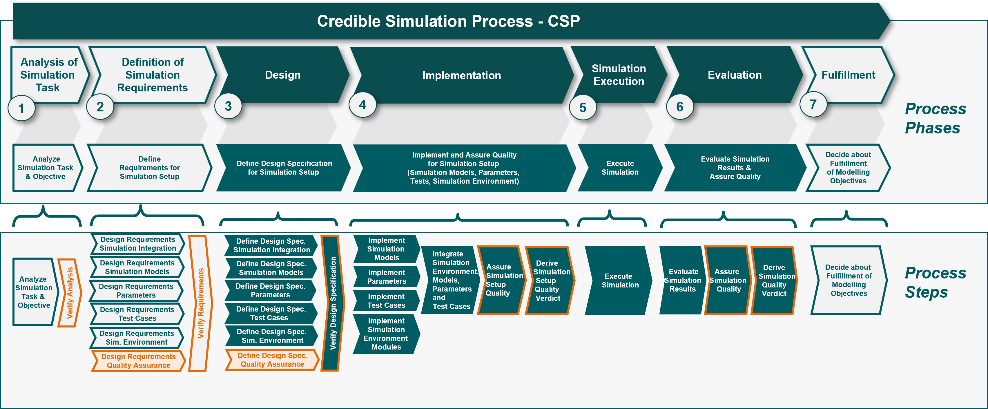
A detailed description of the Credible Simulation Process Framework is available as [CSP]. <<im-csp-details> shows a more detailed structure of the Credible Simulation Process. Each phase is further divided into sub-elements called process steps. These steps have a uniform structure, as is also known from process descriptions:
-
Inputs
-
Procedure
-
Rationale
-
Outputs
The STMD schema maps this structure. In the application, the existing information of a simulation task can now be linked accordingly.
3.1. Allocation and Linking of Information
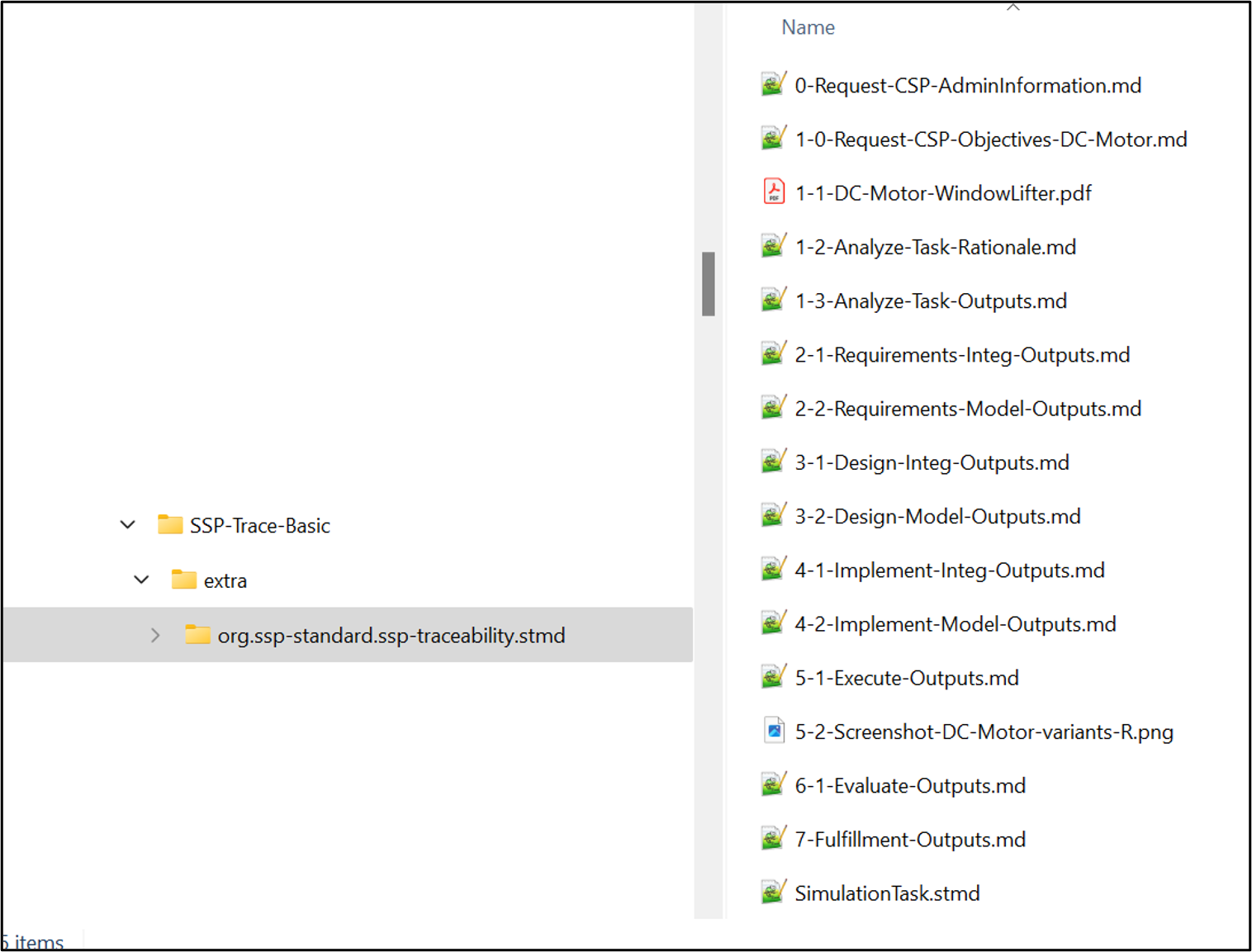
The SSP structure has been supplemented with a directory extra for layered standard extensions.
Each layered standard has its own specific folder, e.g., for the simulation task org.ssp-standard.ssp-traceability.stmd.
The necessary information and files specific to the SSP layered standard are then stored in this folder.
Figure 5 shows the structure for the example explained below.
For ease of understanding, the files are numbered according to their logical order.
The last file shown here is the simulation task meta data file (.stmd), which contains the structure and links of the information.
3.1.1. Linking Information in the STMD File
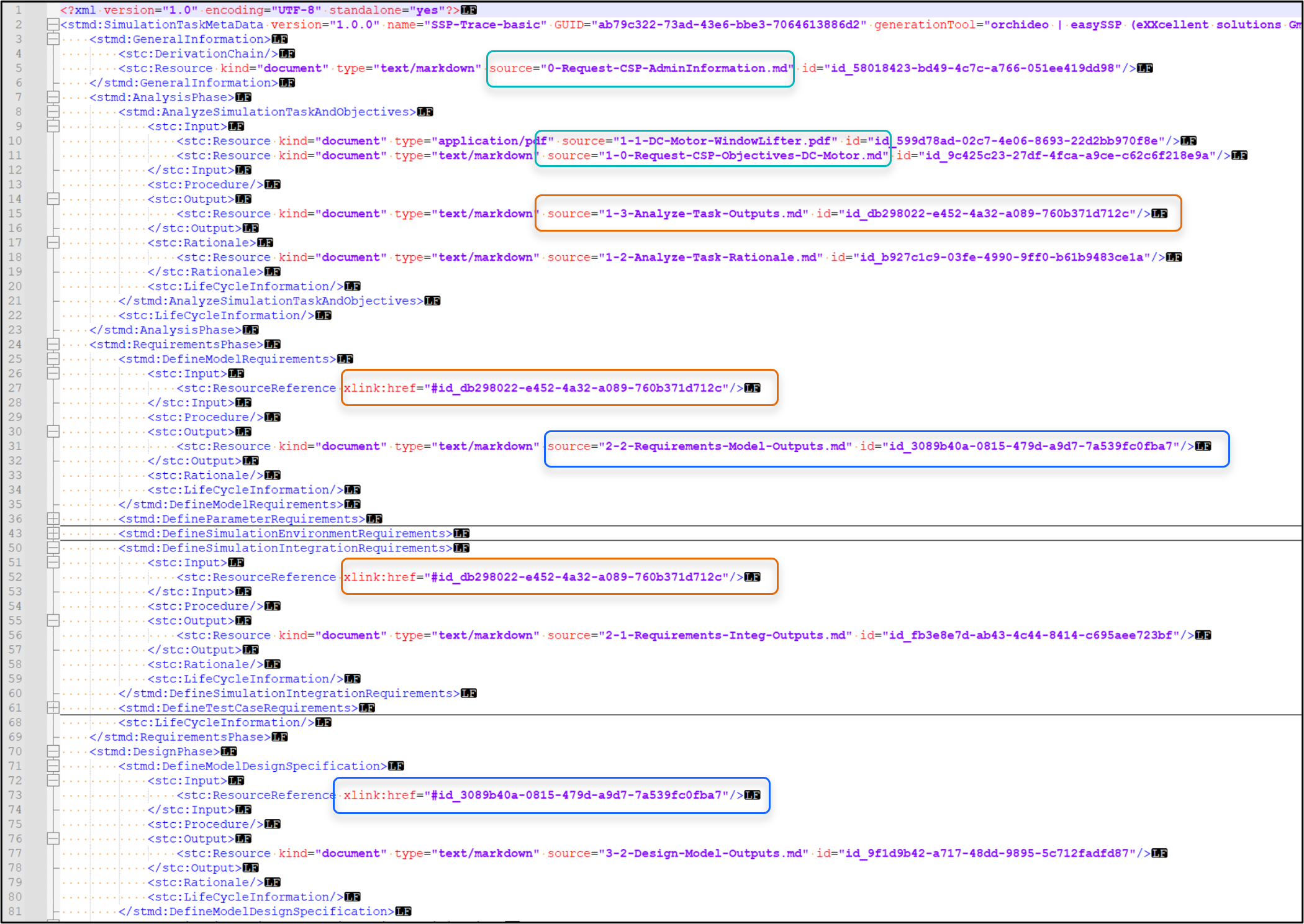
Figure 6 shows how and where information is linked in the STMD schema. The STMD XML schema maps a simulation process. Information and files can now be linked to the appropriate locations within it according to their content.
3.1.2. Information from Simulation Request
A simulation request typically contains administrative information and information describing the simulation task. The administrative information is necessary for linking to the commissioning processes, development, (name of the product, product development, simulation task, commissioning agency, etc.). When describing the simulation task, information is required about what is to be examined and simulated, the name of the item to be simulated, and the objectives of the simulation. This information from the simulation request can be provided as a single file or separated into administrative and content-related information. The administrative information is linked under administrative information. The information describing the simulation task is linked under Input in the Analysis Phase. Any number of sources can be linked here, e.g., a Markdown description and a supplementary PDF. If the information is only available in a single file, this file can be linked to several places.
3.1.3. Linking to Phases, Steps, Inputs, Outputs
The location of the links to the information should allow assignment to specific phases. For larger simulation tasks, a distinction is made within the phases as to whether this information is specific to the models, parameterization, etc. These steps have a uniform structure, as is also known from process descriptions:
-
Inputs
-
Procedure
-
Outputs
-
Rationale
If complete traceability of all details is required, the following should be linked under
-
Inputs:
-
all information necessary for processing
-
-
Procedure:
-
all information used for processing
-
-
Outputs:
-
the results that were achieved
-
-
Rationale:
-
information on why it was done this way is important for quality assurance
-
In the example, this is done for the Analysis step. The results under Output are then linked as input to the subsequent phase, Steps (see markings in Figure 6).
In practice, for example, in the design specification phase, there is often only one common source of information for models, parameters, test cases, and simulation environment (tooling), where the interaction is also described. In such cases, this information should be linked in the simulation integration step.
If complete traceability of all details is not required, however, at least the information in the outputs of all phases should be available. This also enables traceability, with the restriction that it is not possible to directly trace which information was used to achieve the output.
3.2. Metadata
Metadata serves to provide keywords. In the SSP LS Traceability Layered Standard, the classification element was introduced for this purpose. Metadata (classifications) can also be combined into a separate Simulation Resource Meta Data (SRMD) file.
3.2.1. Usage of Metadata
-
Metadata can be created and used directly as classifications
-
Created and linked as an SRMD file
-
Attached to linked sources as classifications (metadata), see Figure 7, red frame
-
Metadata as an SRMD file in FMUs
3.2.2. Metadata using Example General (Administrative) Information
The following example shows that there are several options for placing administrative information in the STMD file, see Phase Admin
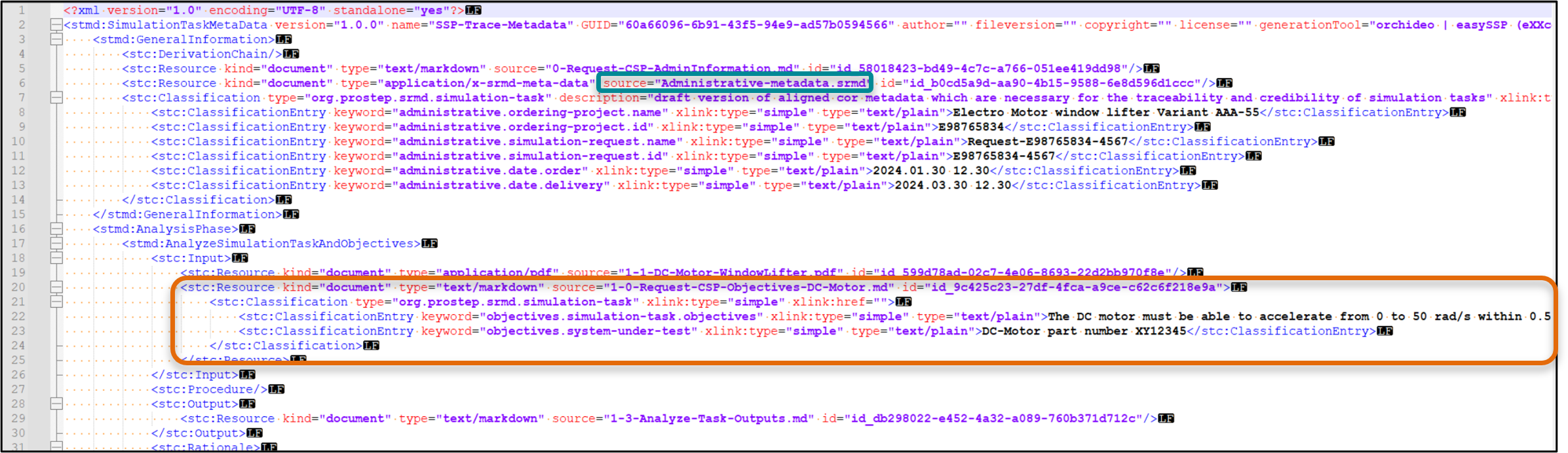

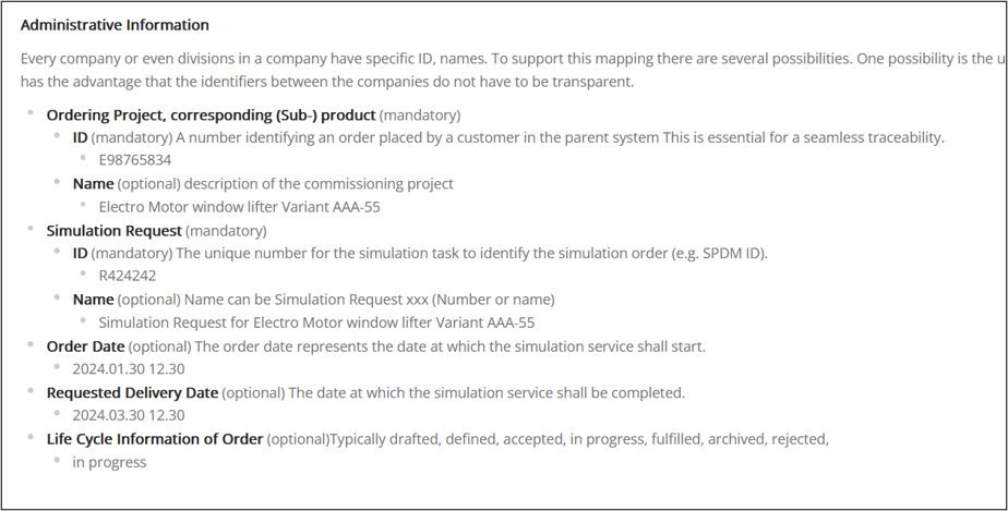
The options are equivalent. Which approach you choose depends on the form in which the information is available and how the simulation task is to be further evaluated. A request file can also be included, and some relevant metadata can be attached as classifications. Here, however, it is important to note what is the single source of truth and what are copies or interpretations in the metadata.
3.2.3. Structuring and Multiplicity of Metadata
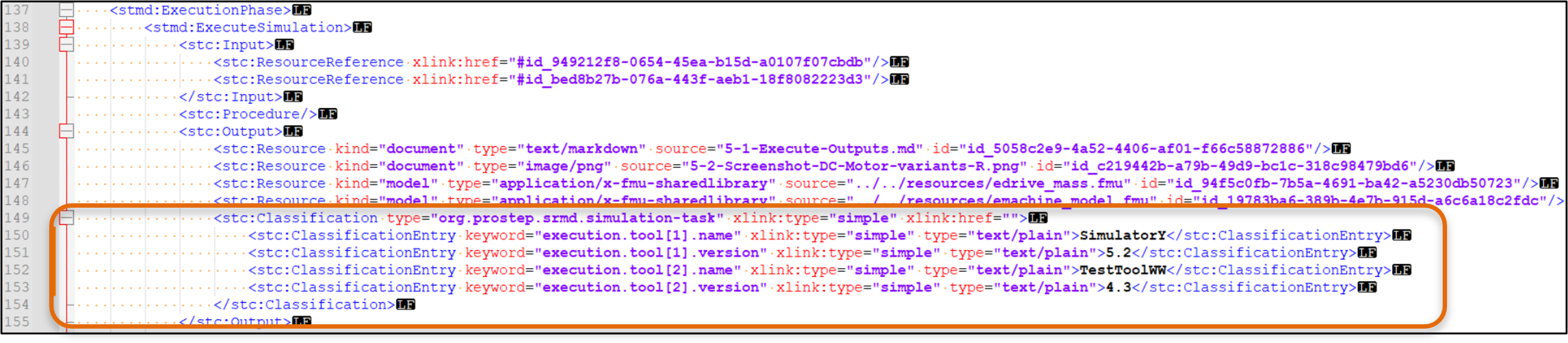
The SSP LS Traceability supports metadata with the classification approach (details see at the specification). It is important that namespaces are defined using “type.” This makes it possible to define specific attributes as desired and means that they do not have to be aligned globally. Multiplicity of classifications are possible, so for example the classification parameter can be used several times to list a set of parameters. The classification schema was deliberately kept simple so that it can be supported relatively easily by tools. Therefore, it does not support sub-structuring or other features. The ordering of classification has no syntactical meaning.
-
If structuring is needed, this can be done using naming conventions, e.g., using dots (execution.tool.name and execution.tool.version).
-
If a kind of grouping is needed, like for two tools to express their names and version, the Modelica convention of brackets and numbers can be used (see Figure 10).
3.2.4. Metadata for Basic Use Cases
The information and metadata required depend on the use case. The following proposes a set of metadata that enables basic functionality for search, analysis, reuse, and traceability. A key factor for user acceptance is that most of this information can be provided by the used IT systems. The listed process phase "Administrative" is not a phase itself but it is part of the STMD-File and contains the relevant administrative information. This set of metadata can be used as starting point in implementation metadata for simulation.
| Attribute Name | Process Phase | Classification | Description | Typical Source |
|---|---|---|---|---|
Ordering project |
Administrative |
administrative.ordering-project.name |
Unique name of the ordering project |
Project management tool |
Specific Product |
Administrative |
administrative.specific-product.name |
Unique name of the specific product |
Project management tool |
Simulation Request |
Administrative |
administrative.simulation-request.name |
Unique name of the Simulation Request |
Project management tool |
Simulation task |
Administrative |
administrative.simulation-task.name |
Unique name of the simulation task |
Project management tool |
Item under Test |
Analysis |
analysis.item-under-test.name |
System, component, or product being analyzed |
Tool / system |
Simulation Objective |
Analysis |
analysis.simulation-task.objectives |
Objective or purpose of the simulation |
User |
Quality criterion |
Analysis |
analysis.quality-aspects |
Criteria used to evaluate simulation success |
User |
Used Model |
Execution |
execution.model.name |
Model used for the simulation |
Tool / system |
Used Parameter |
Execution |
execution.parameters.name |
Parameter used for the simulation |
user (selection) |
Used Tool |
Execution |
execution.tool.name |
Tool used for the simulation |
Tool / system |
Task status |
Fulfillment |
fulfillment.task-status |
Is the task still in progress abortet, finished |
User |
Quality fulfilled |
Fulfillment |
fulfillment.quality |
Documentation of the quality fulfillment decision |
User |
Objectives fulfilled |
Fulfillment |
fulfillment.objectives |
Documentation of the objectives fulfillment decision |
User |
The following illustrates how this information is linked to the development and simulation process.
Decision Task
      |
      v
Simulation Request
      |
      v
Simulation Task
      |
      v
Simulation Results

Simulation Results --> Search
Simulation Results --> Analysis
Simulation Results --> Reuse
This minimum set of metadata can already be used to perform basic evaluations, searches and reuse.
Basic Use Cases
-
I am looking for the corresponding simulations for a project
-
For which applications was Model Z used?
-
In which simulations was a tool used in Version X with models of Version Y
-
Which existing simulation settings can possibly be used as a template for a new simulation task?
4. Design Specification with SSP, SSP LS Traceability
The SSP standard [SSP201] is intended to support
-
the exchange of interconnected simulation models and their parameterization, and
-
the simulation design by specifying empty components through their interface templates
In a simulation request, it is generally sufficient to describe the simulation task and its objective. However, no further specifications are made regarding the type of simulation and the models used (as in the example in Figure 5 and Figure 6).
However, more detailed information, such as design specifications or parts of the implementation and test environments, is often specified.
A simple example is provided in the chapter examples (see Figure 13 and SSP-Trace-DesignSpec.ssp), the electromagnetic part of the DC motor is transferred as an FMU, while only the shell description with interfaces is provided for the mechanical part.
It makes sense to use SSP LS Traceability directly as a container for the artifacts here.
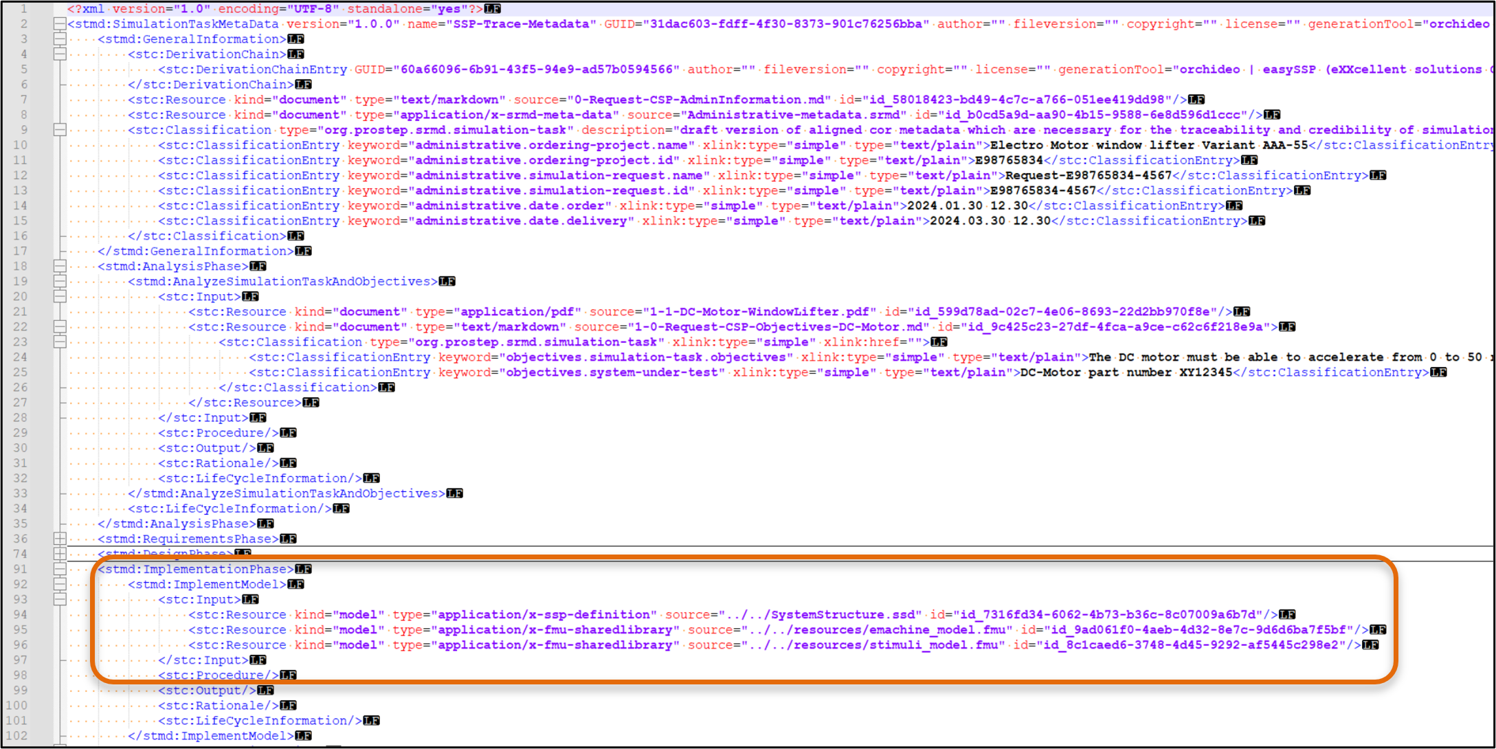
The FMUs whose interconnection is specified as SSD are linked as inputs to the implementation phase (Figure 11).
This approach makes it possible to trace what was input and what was created in the simulation task itself.
5. Data Management and Versioning
5.1. SSP LS Traceability for Data Exchange
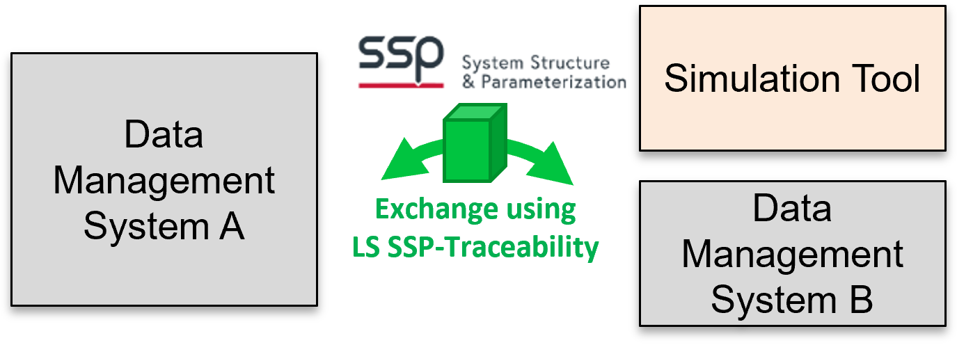
All common data management systems support configuration, versioning, metadata, and labeling, especially for metadata, but usually as proprietary specific implementations. The SSP LS Traceability now supports the exchange of information between these systems and to and between simulation tools in a standardized form (Figure 12).
5.2. Using GitLab, GitHub for Data Management
A simple implementation of data management when using GIT is that the zip structure is unzipped directly in GIT and stored and managed in this way.
6. SSP LS Traceability Examples
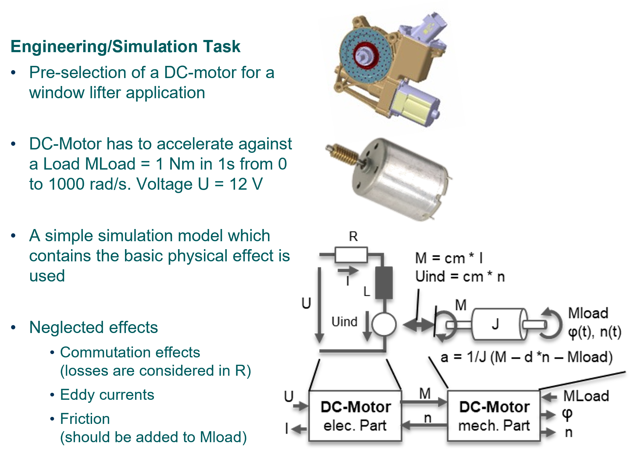
All examples are based on the simulation task of a DC-motor (see Figure 13).
-
Linking of Sources
-
Usage of metadata
-
Simulation of a DC-motor with basic additional information
-
Simulatable on every tool which supports SSP.
-
-
Example with Simulation request which contains design specification
-
Figure 11 is taken from this example.
-
-
Example with extended information set, design specification, simulation
-
covers also modeling and testing of a sub-model
-
As an extended example 5 also contains the design specification and the test environment for the mechanical part of the DC motor. This example also includes a large amount of documentation and metadata. The amount of documentation depends on the required level of traceability and comprehensibility, as this involves a certain amount of effort.
Glossary
The following list of terms and, where given, abbreviations serves to explain typical technical terms related to the Glue Particle approach. This list explicitly does not represent any technical vocabulary from the engineering context.
| Term | Abbreviation | Explanation |
|---|---|---|
Boundary model |
Models of the elements whose interaction with the core model (SuT) should be taken into account |
|
Core model |
The simulation model that is to represent the system under test. In the case of SW the SW |
|
Credible Modeling Process |
CMP |
|
Credibility documentation |
||
Credibility of simulation |
see chapter CSP |
|
Credible Simulation Process |
CSP |
|
Environment model |
Subset of boundary models: Models of the (non-technical) environment in which a system under test operates (roads, traffic, weather, etc.) |
|
Glue Particle |
entfernen |
|
Intellectual Property |
IP |
|
Model |
in this context always simulation model |
|
Model Identification Card |
MIC |
Standard/recommodation from SystemX for Model Meta Data |
Modeling request |
||
Modeling task |
||
Product Lifecycle Management |
PLM |
|
Quality |
Schauen was in CSP schon definiert ist |
|
Simulation environment |
The "simulation environment" describes the complete tooling that is needed to run and evaluate a simulation (simulator, pre-processing, post-processing, test tool, data- and workflow management, …)without simulation models. |
|
(Simulation environment) module |
Elements of the simulation infrastructure which are used and have to be developed or adapted. this can be done in separate subprocesses (similar to model development process), like pre/post-processing functions |
|
Simulation-based Engineering Task |
SbET |
|
Simulation Model Metadata |
SMMD |
|
Simulation objectives |
||
Simulation request |
||
Simulation setup |
The simulation setup includes all elements needed to run and evaluate a simulation. These are the simulation models, the parameters, the test cases, the simulation environment and their interaction. The interaction is usually described in workflows. |
|
Simulation task |
||
Simulation Task Meta Data |
STMD |
|
Single decision process |
||
System under Test |
SuT |
Determination of what is the system to be considered (DC motor, SW) |
Test case |
Typical applications of the CSP are System Analysis, Optimization and Test. The CSP differs here only in some specific aspects. For better readability, the synonym "test" is used for System Analysis, Optimization and Test. |
|
Verification and Validation |
V&V |
References
-
[RFC2119] Bradner, S.: Key words for use in RFCs to Indicate Requirement Levels. RFC 2119, March 1997. https://www.ietf.org/rfc/rfc2119.txt
-
[SEMVER200] Preston-Werner, T.: Semantic Versioning 2.0.0. https://semver.org/spec/v2.0.0.html
-
[SSP201] Modelica Association: System Structure and Parameterization 2.0.1. May 2026. https://ssp-standard.org/docs/2.0.1/
-
[SSPLST] Modelica Association: SSP Layered Standard Traceability Version 1.0. August 2025. https://ssp-standard.org/ssp-ls-traceability/1.0.0/
-
[MIC] prostep ivip, IRT SystemX: MIC-Core 1.2. September 2025. https://mic-core.github.io/MIC-Core/main/
-
[SIC] prostep ivip, IRT SystemX: SIC-Core 0.1. May 2026. https://mic-core.github.io/MIC-Core/main/
-
[CSP] prostep ivip: Credible Simulation Process Framework in prostep ivip SmartSE Recommendation 2025 PSI 11 V4.0 Part H: https://www.prostep.org/en/medialibrary/detail?ai%5Baction%5D=detail&ai%5Bcontroller%5D=Catalog&ai%5Bd_name%5D=prostep-ivip-smartse-recommendation-2025-psi-11-v-4-0-part-h-credible-simulation-process&ai%5Bd_pos%5D=2